
 Trolley Scan(Pty) Ltd
Trolleyponder®/EcoTag®
Mike Marsh,
Managing Director,
Trolley Scan (Pty) Ltd,
South Africa
Copyright Trolley Scan (Pty) Ltd 2002
 Recent developments in the semiconductor and radio industries have seen
the arrival of single chip low cost transponders that can operate in the
860-930 MHz UHF band. This is one of the ideal frequencies for this technology,
being a compromise between range performance and transponder antenna size.
Recent developments in the semiconductor and radio industries have seen
the arrival of single chip low cost transponders that can operate in the
860-930 MHz UHF band. This is one of the ideal frequencies for this technology,
being a compromise between range performance and transponder antenna size.
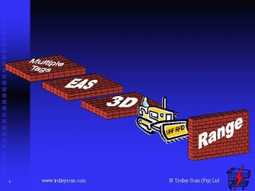
Range is a key issue in making a universal low cost ubiquitous RFID systems
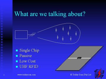 Passive RFID systems operate by a reader providing an energizing field,
RFID transponders that fall into that field collecting some of the energy
from that field to operate their electronic circuitry, and the transponder
communicating its data back to the reader powered from the energy of that
field.
Passive RFID systems operate by a reader providing an energizing field,
RFID transponders that fall into that field collecting some of the energy
from that field to operate their electronic circuitry, and the transponder
communicating its data back to the reader powered from the energy of that
field.
The key issue in getting effective range from the energizing field
is to use the energy propagation efficiently. This results in the designer
choosing an operating frequency, which impacts the size and form of the
transponder and the operating range.
 Historically
when operating ranges for passive transponders were very short - a few
centimeters - and there could only be one transponder in the reader field
at a time, there was no concern about the communications being corrupted
by two transponders interfering with each other.
Historically
when operating ranges for passive transponders were very short - a few
centimeters - and there could only be one transponder in the reader field
at a time, there was no concern about the communications being corrupted
by two transponders interfering with each other.
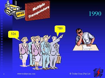
As technology advanced
it became possible to have operating distances measured in meters, and
the major hurdle became how to handle many transponders in the zone at
the same time, especially if the transponders were to be very simple and
to use only one communication frequency. Due to the transponders having
weak communication signals, they would not be heard by the other transponders
that were also in the energising field at that time.
This situation can
be likened to a hall containing many blind and deaf persons, each with
an identity number, trying to communicate their identity to a person on
the stage who is also blind.
 A major
advancement in the fortunes of low cost UHF RFID happened with the discovery
by the author of a protocol to resolve this communication problem at a
place called Arbeidsaamheid in Pretoria, South Africa in November 1990
while working for the South African Government Council for Scientific and
Industrial Research.
A major
advancement in the fortunes of low cost UHF RFID happened with the discovery
by the author of a protocol to resolve this communication problem at a
place called Arbeidsaamheid in Pretoria, South Africa in November 1990
while working for the South African Government Council for Scientific and
Industrial Research.
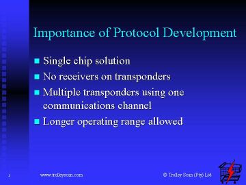
This was a very important break through as it allowed a single chip transponder to be produced that would have no tuned circuitry and yet allow a large number of passive transponders to communicate to a reader on a single communication channel.
In order to give a physical
demonstration of the potential of this protocol, developed under the code
name of "Post Toasties" a retail application was developed to
show how this protocol could be used in a supermarket situation.
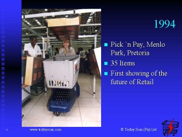
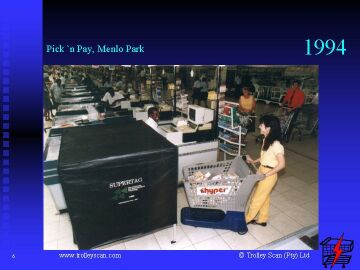 To demonstrate the concept, it was shown to the public on
the 11th January 1994, by scanning a trolley containing 35 items in the
Pick 'n Pay supermarket at Menlo Park in Pretoria.
To demonstrate the concept, it was shown to the public on
the 11th January 1994, by scanning a trolley containing 35 items in the
Pick 'n Pay supermarket at Menlo Park in Pretoria.
This launch was shown to more than 300 million viewers via 650 TV stations
that leaked the news item a few days before the press embargo ended.
 Approximately 2000 companies phoned in over the next few
days expressing interest in the technology.
Approximately 2000 companies phoned in over the next few
days expressing interest in the technology.
The importance of this demonstration was that it showed the potential for low cost RFID to be used as a replacement technology for barcoding in the retail environment.
An interesting aside is that this demo happened with one of the first plastic
trolleys available in South Africa. Since that time plastic trolleys are
a major force in the country, not driven by the RFID issue.
With the South African
government's changes in scientific policy that were happening in 1994, Mike Marsh and Trevor Hodson
left the CSIR and the inventions behind, and formed their own company.
In 1995 Trolley Scan was formed and in 1998 they developed a new protocol
which was called the Trolleyponder® protocol.
 To explain the features of this new protocol, consider a room full
of blind and deaf persons, where they are divided into different groups
and call out a colour, such as RED or BLUE, and you still have a blind
person on the stage writing down how many persons there are of each group
in the audience.
To explain the features of this new protocol, consider a room full
of blind and deaf persons, where they are divided into different groups
and call out a colour, such as RED or BLUE, and you still have a blind
person on the stage writing down how many persons there are of each group
in the audience.
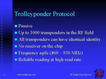 Features of Trolleyponder protocol
are that
Features of Trolleyponder protocol
are that
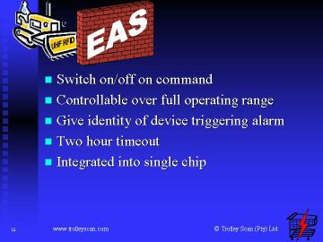 Electronic Article Surveillance, or
EAS systems are widely used in retail situations to discourage shoplifting.
In RFID designs, it is possible to add EAS features to the chip design
to include the EAS properties.
Electronic Article Surveillance, or
EAS systems are widely used in retail situations to discourage shoplifting.
In RFID designs, it is possible to add EAS features to the chip design
to include the EAS properties.The Trolleyponder design included features for EAS that
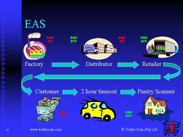 An example of the use of controllable
EAS in the manufacturing/retailing industry would be where a manufacturer
makes some item for eventual sale to a consumer. The RFID tag with EAS
features is attached at point of manufacture.
An example of the use of controllable
EAS in the manufacturing/retailing industry would be where a manufacturer
makes some item for eventual sale to a consumer. The RFID tag with EAS
features is attached at point of manufacture. When ready for delivery to the Wholesaler the goods are invoiced and the EAS features activated. The goods are then loaded onto the truck passing through an EAS detection field which lets all goods properly invoiced pass without activation of alarms, while sensing any goods being added to the truck that were not correctly invoiced.
When the truck arrives at the wholesaler, the wholesaler deactivates the EAS features when unloading the truck via his RFID reader.
On invoicing the goods to the retailer, the process is repeated. Eventually a consumer purchases the goods and can checkout of the store via a system such as Branders which allows unmanned checkouts with full EAS checking.
Two hours
later the EAS features switch themselves off allowing the consumer to monitor
the provisions in her pantry with a US$30 reader which can be linked to
her computer for automatic re-ordering.
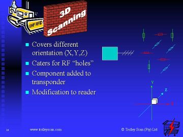 A significant problem to the application
of RFID, is that of a property of radio energy transfer called polarisation.
This requires a reader and a transponder to have the same orientation in
order for energy transfer to happen successfully.
A significant problem to the application
of RFID, is that of a property of radio energy transfer called polarisation.
This requires a reader and a transponder to have the same orientation in
order for energy transfer to happen successfully.
Another problem that is unique to passive transponders is the interaction in the energising field between the signal that travels directly from the reader and that which bounces off a wall or floor and arrives at the transponder with a different phase. This can cause "holes" to appear in the energising field, spots where a transponder is receiving no power despite it being close to a reader.
Trolleyponder addresses this situation in the single chip design which
 The purpose of the above history is to place in context the importance
of achieving good operating range with this single chip RFID design to
make a "one part fits all" solution.
The purpose of the above history is to place in context the importance
of achieving good operating range with this single chip RFID design to
make a "one part fits all" solution.
The operating range performance of a passive transponder is primarily governed by the choice of operating frequency. This is due to the effect of frequency on efficient coupling of energy from the reader to the transponder.
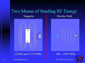
Energy transfer by means
of radio waves occurs either via an electric or magnetic field transfer.
The magnetic field drops off very quickly and it is difficult to propagate
sufficient energy to power a transponder at a distance.
The electric field
travels forever. Even out in space, a sensitive detector would be able
to pick up the field if desired.
 When to use magnetic and when to use electric propagation is governed
by practical restraints of antenna size and the very high speed at which
light and radio waves travel.
When to use magnetic and when to use electric propagation is governed
by practical restraints of antenna size and the very high speed at which
light and radio waves travel.
Below 100MHz operating frequency, designers wanting efficient energy transfer would use the magnetic properties, while electric would be favoured above this frequency.
Magnetic coupling is characterised by coils being used to launch and receive the energy. Range is limited by how far from the North South Axis one can move the field lines for energy transfer. By increasing the size of the reader coils additional range can be found, but getting beyond 1 meter is difficult. 125 Khz & 13.56MHz utilize this form of energy transfer.
Electric coupling is practical above 100 MHz from a physical antenna size point of view, Energy travels indefinitely giving one quarter power density every doubling of distance.
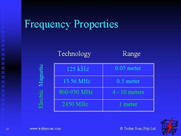 This table shows why the 868(European Union/GSM)/915(US)MHz
bands are becoming the preferred frequencies for UHF RFID systems.
This table shows why the 868(European Union/GSM)/915(US)MHz
bands are becoming the preferred frequencies for UHF RFID systems.
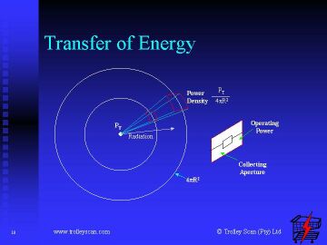 The reader radiates energy from its antenna, which
travels away from the reader at the speed of light in all directions.
The reader radiates energy from its antenna, which
travels away from the reader at the speed of light in all directions.
At any instant of time, that energy is distributed equally over a sphere centered on the reader and radius equal to time traveled times speed of light.
As the surface area of a sphere quadruples every doubling of the radius, the energy density quarters every time the radius doubles, a process that continues even into deep space.
The transponder collects this passing energy to use
as its operating power over an area around the transponder antenna that
is referred to as the antenna aperture.
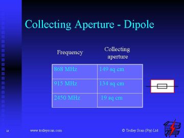 The area over which the antenna at the transponder collects its energy
is related to the operating frequency squared.
The area over which the antenna at the transponder collects its energy
is related to the operating frequency squared.
For development and comparison, dipoles are favoured for UHF transponder design as they are simple to make, and their performance is exactly known.
The difference between the aperture
area at 868Mhz and 915MHz is small giving similar performance. The aperture
for the 2450MHz frequency has become so small that this becomes the practical
upper limit at which passive transponders operate. To compensate for the
smaller aperture, a 2450MHz system would need 7 times the reader power
to give the same performance as the 868/915 MHz systems.
 In order to monitor improvements in performance, we need to have a
clearly defined and measurable parameter so that we can quantify the state
of the development.
In order to monitor improvements in performance, we need to have a
clearly defined and measurable parameter so that we can quantify the state
of the development.
Transponders are a combination of electronic circuits and antennas, which have electronic and radio frequency parameters that impact their overall performance.
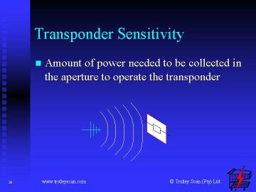
To quantify the performance of this element,
Trolley Scan have introduced the parameter called Transponder Sensitivity
which is defined as the amount of power needed to be collected in the aperture
of the transponder antenna for the transponder to operate correctly.
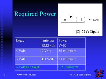 The circuit diagram shows the preferred method of converting
electric field RF energy collected in the antenna aperture to DC power
for operating the integrated circuit.
The circuit diagram shows the preferred method of converting
electric field RF energy collected in the antenna aperture to DC power
for operating the integrated circuit.
The antenna receives the RF energy and in the case of a dipole converts it from the impedance in air of 377ohm, to 72 ohms at the output terminals of the antenna. Schottky diodes rectify and double the voltage at the terminals of the antenna storing the energy in the capacitor.
Due to the low impedance of the antenna, the power needed to operate this circuit is dependant on the voltage needed for the electronic circuit, and the impedance of the antenna.
In the case of a 5 volt logic circuit, that is a circuit that needs the voltage on the capacitor to be greater or equal to 5 volts, with the voltage doubling and converting AC to DC, only 2 volts of RF energy would be needed at the terminals of the antenna, which equates to 55 milliwatts of power at 72 ohms. This configuration is what is used as a standard transponder for comparison purposes.
In the case of a 3 volt circuitry on the transponder, 23 milliwatts of power will be needed.
These powers are the minimum powers needed for the transponder circuit, irrespective of the current consumption of that circuit.
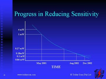
In 2000 Trolley Scan developed EcoTag® technology to lower the minimum power consumption needed to operate the transponder.
The impact is that currently transponders
needing only 0.27milliwatts of power are practical.
EcoTag is a patented method and apparatus that realizes much lower operating powers from UHF RF transponders than that available from an electronic circuit attached to an antenna.
With the advance in semiconductor technology, the RF power levels needed to operate the EcoTag transponder are continually falling and already tests have been carried out on a transponder needing just 0,084milliwatts (84uW).
This is all achieved
in a single chip transponder with a metal foil/ink antenna, while maintaining
the wide operating frequency needed for frequency agility for international
trade.
 The importance of EcoTag developments
on the future of UHF RFID cannot be under estimated.
The importance of EcoTag developments
on the future of UHF RFID cannot be under estimated.
Frequency regulators have inherited passive RFID which they have to fit into the spectrum plan for the region, and it wants to be in the 860 to 930MHz for maximum effectiveness. Radio regulations typically cater for non-interference with sensitive radio receivers with virtually no plans around energizers. Therefore we are in a situation where regulations limit what performance one can achieve with passive RFID. In the US the regulations are much more liberal in that they have a plan for energisers and have allocated a wide ISM band from 902 to 930MHz particularly suited to passive RFID.
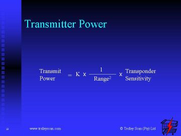
The radio propagation equations show that
Transmit power = constant(k) * Transponder sensitivity / (Range2)
Any lowering of the Transponder sensitivity results in a similar lowering
of the Transmit power, or an improvement in the operating range at which
the transponder can operate on the same energising field.
 Although most users might not
want the increase in range as the major benefit from the use of EcoTag
technology, it also equates to a lowering of the reader energising power.
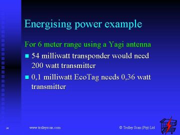
To operate at 6 meters using a standard 54 milliwatt transponder, a transmitter
the size of a cell phone base station (200 watts) would be needed,
Although most users might not
want the increase in range as the major benefit from the use of EcoTag
technology, it also equates to a lowering of the reader energising power.
To operate at 6 meters using a standard 54 milliwatt transponder, a transmitter
the size of a cell phone base station (200 watts) would be needed,
while to operate an EcoTag transponder over the same distance, a transmitter that is inside a cell phone could be used.
Besides the impact of transmitter
size and complexity, environment and safety, there is also the issue of
battery life for portable equipment. All this can be implemented in the
same single chip transponder attached to a simple foil antenna.
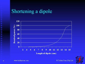
Market feedback indicates that users would prefer a shortened dipole compared to the 15cm length that most efficiently transfers UHF energy.
However shortening a dipole can have drastic results on energy
transfer as shown in this graph.
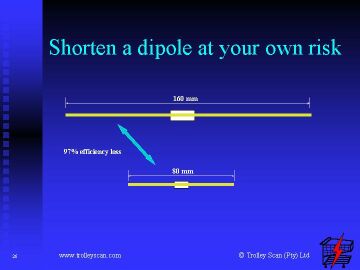
Halving the length of the dipole can lead to a 97% loss in efficiency, which defeats the purpose of developing energy efficient transfer systems for UHF.
A benefit of the EcoTag development is that it does not need conventional
antennas, giving a lot of freedom to the designers to change the shape
of the antenna and hence the packaging of the transponder.
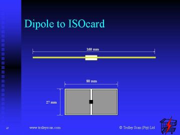
What will most probably be the most produced UHF transponder antenna,
is an 80mm by 27 mm antenna, smaller than the conventional ISOcard format
used by the 13.56MHz technology, and which has virtually 100% of the performance
of a half wave dipole. It can be packaged in an ISOcard access control
format for persons, animal tag for herd animals, or as a sticky label for
books, files and parcels - while still maintaining the single chip with
foil antenna approach.
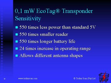
By the end of 2002 we expect 0.1 milliwatt (100uw) transponders to be available commercially.
What this means for the user is
Behind all developments, Trolley Scan have been developing this technology focused on the eventual use for the retail industry.
Due to its excellent fit with many other applications that want the same benefits, and due to limited supplies, it is unlikely to achieve penetration in this sector for some time, even although technically the features are presently available.
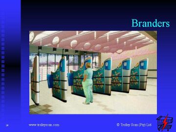
In August 1998 an industrial design student, Ms Le Tong of the Faculty
of Built Environment, The University of New South Wales, Sydney, Australia
designed the Branders systems around the features offered by Trolley Scan.
Branders is the South African Afrikaans word for "waves".
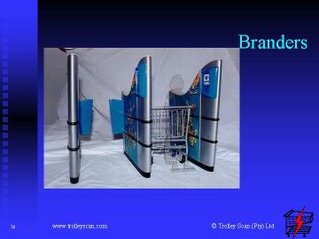
The system provides for unmanned checkout, where the customer places
their packed trolley in the booth, it is read using the 3D scanning features
of Trolleyponder,
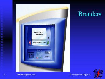
payment is made via the terminal,
the trolley is rescanned this time activating the EAS, the gates are opened
and as the customer leaves
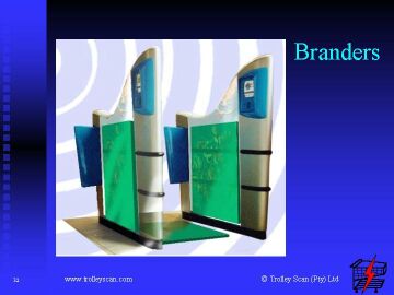
the trolley and the customer
pass through an EAS monitoring field. This system has attracted a lot of
interest from retailers.
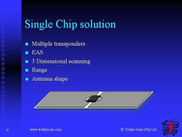
What we have described in
this paper is all implemented in one single chip, attached to a simple
antenna structure.
One of the major contributions by Trolley Scan to the
advancement of RFID must be in its commercialisation strategy. Historically
RFID has been provided in a major part by companies that are large scale
electronic circuit manufacturing companies; such as Phillips, Texas Instruments
and Motorola. Through its commercialization strategy, Trolley Scan have
drastically reduced the barriers to entry for much smaller players allowing
almost any market focused company to become a major provider of this technology.
This is achieved by a
All licensees produce compatible products allowing the user to choose between suppliers.
Trolley
Scan assist with technical guidance where necessary. At the Smart Labels 2002 conference,
Sygade and QuantumTag are the first two companies of the licensees to publicly
announce their licensing of the technology and will be delivering this
technology to the market place shortly.
What we have provided is vision for computer systems, possibly the fourth arm of IT systems after computers, networks and software. Although developments focused on the most challenging problem, namely developing a very low cost RFID solution for retail, it has application in almost all situations where computers need to identify items approaching the RFID readers
Trolleyponder®,EcoTag® and TinTag® are the TRADEMARKS of Trolley Scan (Pty) Ltd